It wasn’t quite the speedrun I anticipated when I first started working on version 2 of the Trophy, but I’m finally ready to call my work done (for now) and ship it off. Here’s a changelog of sorts:
- [Hardware] Mounted the Arduino to the base using standoffs
- [Hardware] Trimmed the cables exiting the trophy body and soldered on header pins for a clean connection
- [Hardware] Glued the base to the trophy body using Amazing Goop
- [Software] Developed and implemented yun-easy-wifi-switch to allow for user-friendly WiFi network switching
- [Software] Developed and implemented linino-to-serial for Linino -> Arduino communication
- [Software] Linino notifies Arduino of boot via linino-to-serial and displays a “loading” message until then (previously displayed nothing until boot)
- [Software] Trophy displays the full message cycle only once an hour via cron + linino-to-serial (previously was always on)
- [Software] Updated the Python code to allow for granular control over the trophy’s message buffer
- [Software] Handle errors thrown by the Kimono API
- [Software] Overhauled the Arduino code to accept communication from Linino and act accordingly
The name of the game for these revisions was an improved user experience. The WiFi switch was by far the most time-intensive task in v2, but it takes a huge amount of configuration responsibilities from the user. The loading text gives immediate feedback that nothing is broken. And the new trophy message cycle (once when Linino boots and then on every subsequent hour) makes the trophy far less annoying.
Here are some pictures of the hardware changes. These changes were also driven by the need to make things easier for the user — basically, taking three loosely-connected things and turning them into one solidly-connected thing. First, I inserted the standoffs by drilling a small hole and hammering them down (nylon threads don’t cooperate with hard wood).
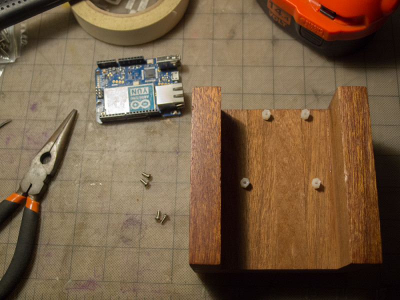
You can see that I slightly messed up the position of the top-right standoff, so that one doesn’t get a screw. Three is all you need!
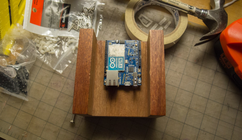
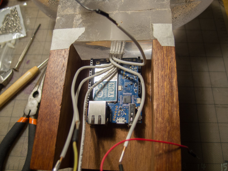
I used masking tape to temporarily connect the trophy to the base. Old me had accidentally placed the embedded copper wires too far forward in the cast, so they butted right up against the Arduino at the point where they exit the resin. I had to trim down the Arduino’s ICSP pins (the 3×2 arrangement of pins in the top-center of the board) to let them clear.
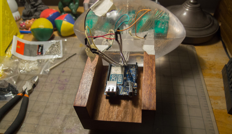
Then I bent the wires in to place. Old me also ordered these incorrectly (see how power and ground cross over the rest of the wires). I couldn’t have flipped the board because the ethernet and USB ports need to be accessible. Not that big of a deal; I had plenty of wire to work with. I bent them to roughly hit the points on the board where they belonged.
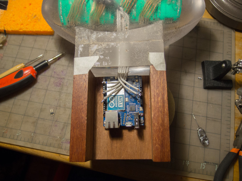
Finally, I snipped the wires to length and soldered a header pin perpendicular to the copper core. I ended up wrapping these with a tiny bit of electrical tape to be extra careful. Overall, it’s pretty solid, especially with the trophy glued to the base (not pictured).
So what for version 3? Probably some aesthetic improvements – perhaps a 1/4″ thick copper strip where the resin joins the wood? Another thing I’d like to add is an “on demand” button so that the trophy’s owner can see the message cycle at their convenience. And of course, doing more with those LEDs besides just scrolling text across them. But that will have to wait until next year! To read about version 1 of the trophy, refer to these posts about its development and fabrication.