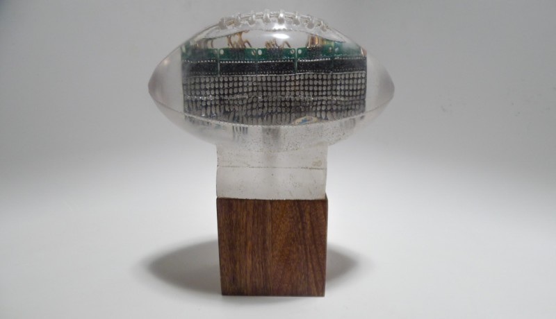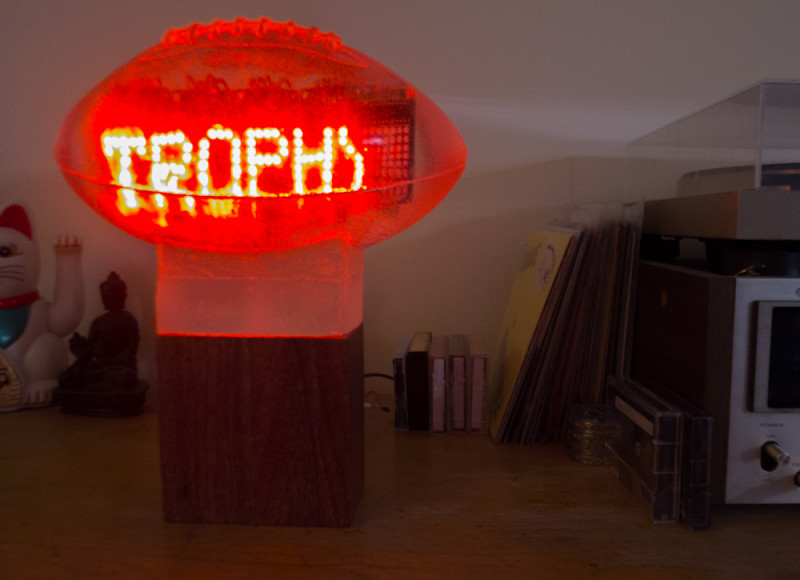
The Trophy of the Future (TotF) is the world’s first internet-enabled fantasy football trophy. Being the second-ever and, at the time, reigning champion of my fantasy football league, I felt it would be appropriate to spend some time at ITP producing a trophy to share with the league, so I made it my final project for Peter Menderson’s Materials and Building Strategies class. This post will cover the fabrication of the trophy. To read about the technology behind it, check out part 2!
A few weeks in to the semester we started making molds, and after seeing how much fun that was I had the initial idea of casting a football in clear resin for the trophy. Inspired by this headphone amplifier Instructable and wanting to throw a tech twist into the project, I decided to also embed an LED matrix in the resin that, by way of an Arduino Yún, would display NFL news, scores, and my league’s champions. In this first part of documentation, I will show the steps that I took to fabricate the trophy.
After sketching out a few ideas, I made this quick-and-dirty prototype trophy using insulation foam that I turned on a lathe. I tried to approximate the dimensions of an NFL football, and then placed it on a plywood base. The prototype made me confident that the simple presentation of a football on a base would adequately symbolize the fantasy power that we fantasy football champions wield. I had earlier floated the idea of the base being an arm and hand holding the ball, but opted for what I feel is the more elegant form. The prototype also helped me figure out what kind of screen I would put inside. Initially I wanted to embed a small LCD monitor in the trophy, the kind you would find in the seat-back of an airplane. The prototype made it obvious that if I did that, I would have to make the football much bigger (which would mean more material cost). And as it would turn out, the only football I could find to make a mold of was smaller than average anyway, so I decided to use an LED matrix instead.
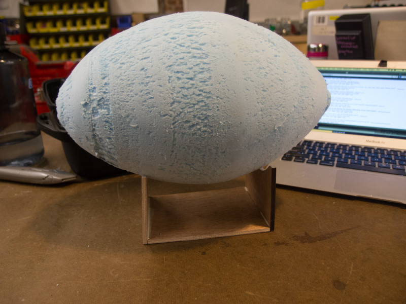
Do note the indispensable /r/fantasyfootball on my laptop in the background. This is also the appropriate time to mention that unfortunately I was unable to successfully defend my championship this season, falling to our league’s commissioner Dave (aka “TurnYourHeadAndCoughlin”) in the championship game.
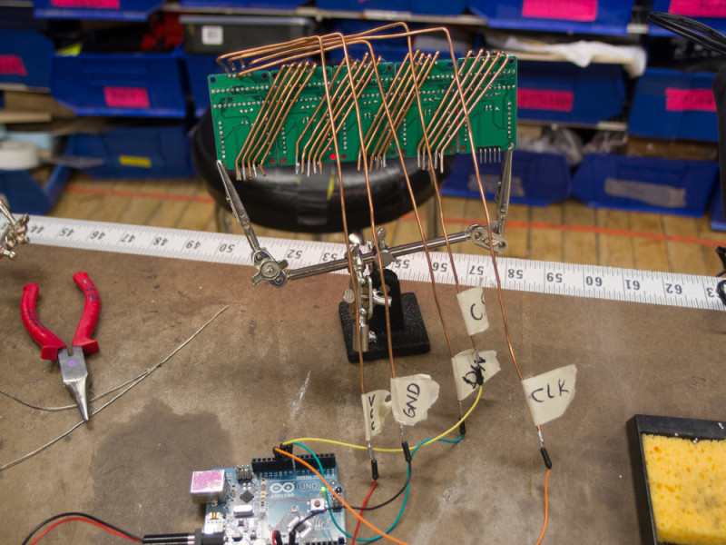
I began fabrication on the final product by assembling and testing the LED matrix. The full matrix comprises five MAX7219 8×8 LED modules chained together. First, I had to assemble the individual matrices, one of which is pictured below.
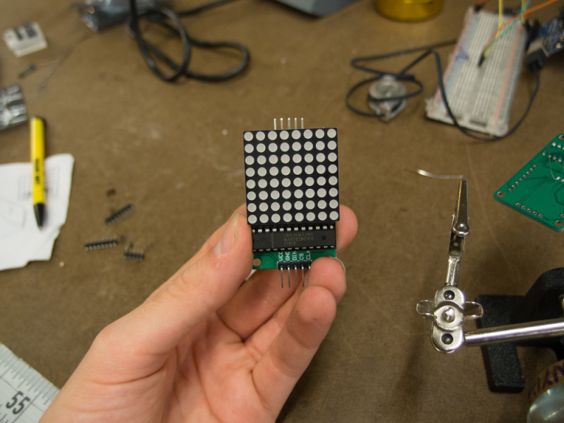
The commercially available modules are not designed for easy chaining, with the output being placed at the bottom of the PCB and the input at the top. This problem has been solved with the Parola PCB, which is a reconfiguration of the same components that places inputs and outputs side-by-side (I note this because I used the Parola software to control the matrix and it deserves the mention being both an elegant physical design solution and a simple and full-featured software library). Unfortunately the Parola hardware isn’t commercially available and it was out of my project’s scope to start diving into custom PCB fabrication, so I was forced to chain my modules in the ribbon-like fashion you see below.
One of the most common questions I got from my peers was “why the heavy gauge wire?” My answer was because I think it looks cool – I was trying to pay homage the headphone amp. In retrospect, this was probably a foolish decision – I still think it looks nice (albeit a little sloppy) – but bending and soldering that wire was a real source of frustration. Bending, aligning and keeping the wire separated was immensely tedious, and the input leads especially kept coming undone (I almost ruined an entire board by accidentally peeling the copper tracing off of the board when trying to reinforce the connection on the voltage input lead). But, thanks to a multimeter and a lot of incremental testing, I had few other issues getting the boards to work.
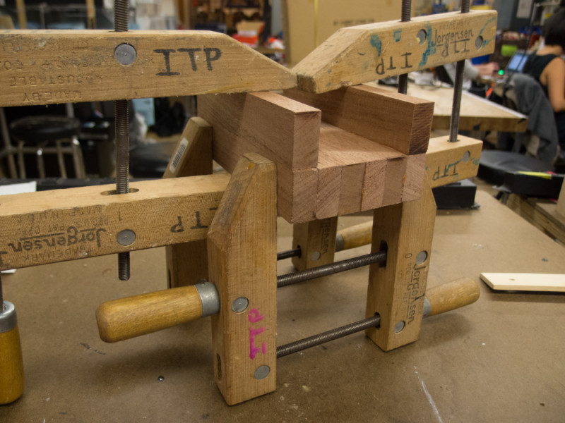
The base is made from pieces of 1×2 mahogany that I glued together as shown below. I cut this longer base into two shorter ones: one to support the football I would make the mold of, and another to support the finished resin cast.
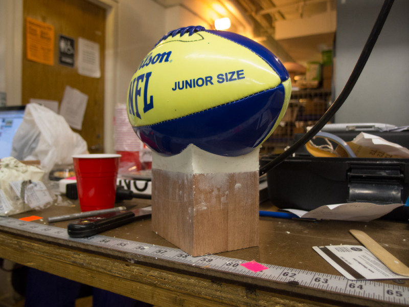
Next I attached my molding football to the base using plasticine. Because I would be making my mold with silicone, it was necessary to use a sulfur-free clay to make this connection – using a natural clay would have prohibited the silicone from curing. Also you will note the unique football I used to make the mold of. It is, as far as I can tell, the only completely smooth football available for purchase. Specifically, it is the Wilson Illuminator, a glow-in-the-dark, junior-sized football made out of smooth PVC. Smoothness was critical because silicone will capture every tiny detail of an object, and I was concerned that the LED matrix would be hard to read through the textured surface of a regular football.
Here it is after being covered with silicone. I used about seven coats of Smooth-On Mold Max STROKE brushable silicone rubber. This was my first time using silicone – we had only worked with alginate in our previous in-class moldmaking exercises – but the process was pretty straightforward. Smooth-On, the manufacturers of both the silicone and the resin I used for this project, produces excellent how-to videos that I recommend you watch whether you ever plan on making a mold or not. They’re extremely satisfying.
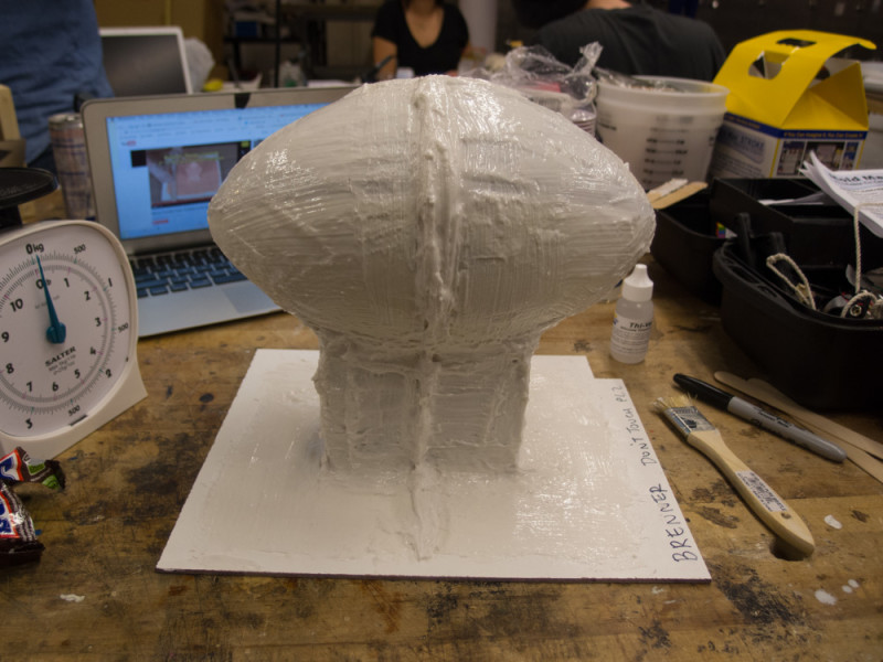
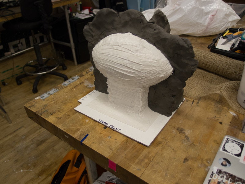
Because silicone is flexible and slightly stretchy, it is necessary to create a hard shell to reinforce the desired form. This is called a mother mold. I made mine in two parts using plaster reinforced with burlap strips. The first step of this process was to build up a clay partition along the center line of the mold (natural clay is okay now because the silicone has already cured). This gave the first half of the mold something to lean up against.
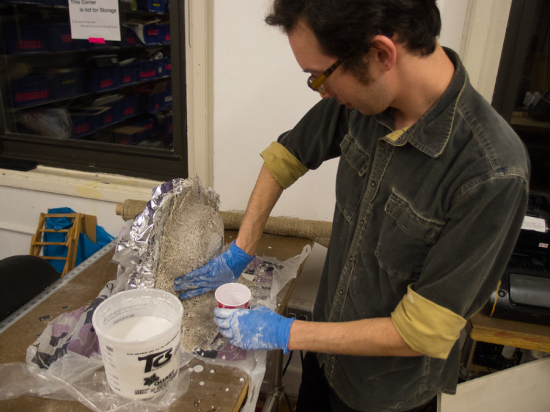
Here I am making an absolute mess with burlap and plaster. Not being too experienced with the material, I found I had a very short window between the plaster being runny and solid in which I had to coat and arrange the burlap strips. Fortunately this part of the process gives you the most room-for-error because it just has to generally fit the form; detail is irrelevant here. Do note the initials “TCS” on my plaster bucket: this stands for The Compleat Sculptor, a sculpting supply store located on Vandam Street here in Manhattan. The staff there was immensely helpful in helping me plan this project out and I couldn’t have pulled it off without them.
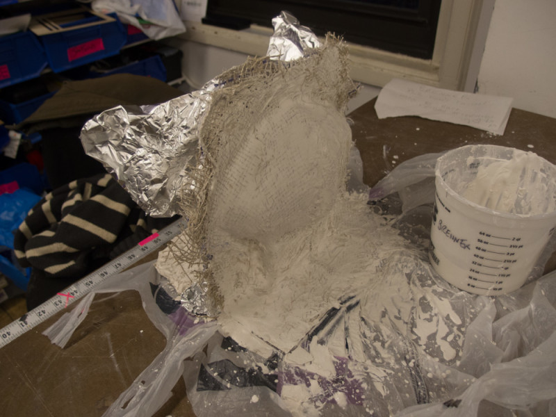
Here is the finished mother mold. The foil is used to keep the two halves from sticking to each other.
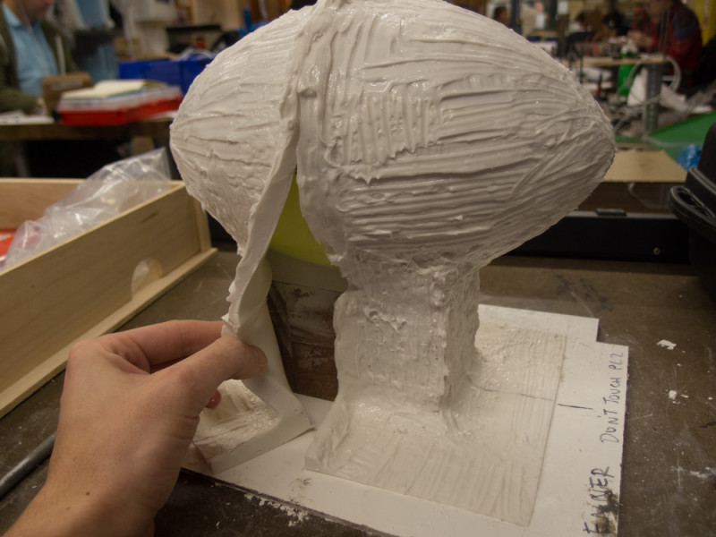
After around 72 hours of letting the plaster fully cure, I was finally able to remove the mother mold and cut open the silicone. I cut it along the thicker part of the mold (when applying the brush on silicone, I used a thickening agent to give me this reinforced cut seam).
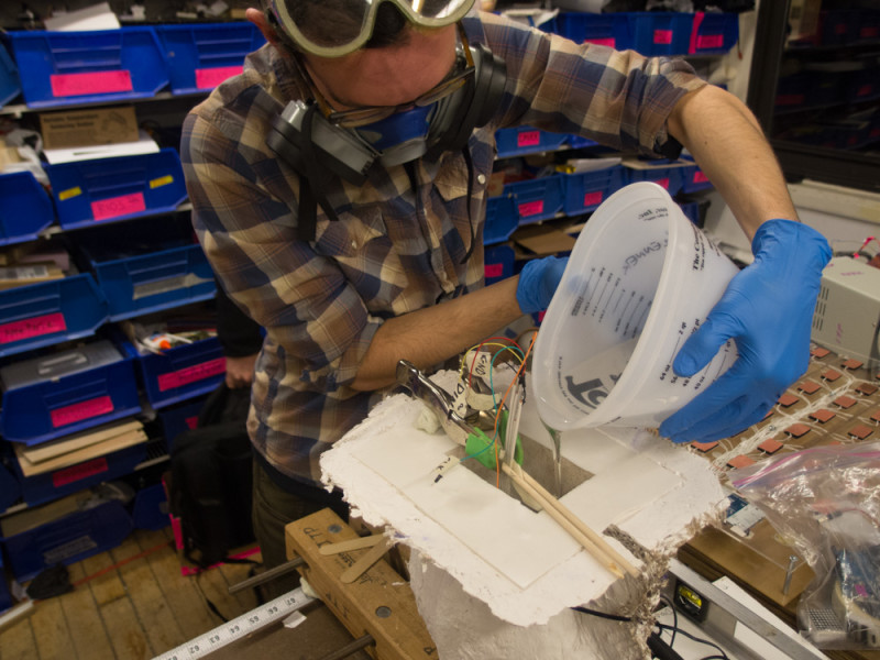
With the original football and base removed, I was finally able to cast the resin. With the silicone and mother mold secured upside-down and with the assembled LED matrix suspended in the middle, I poured a gallon of Smooth-On’s Crystal Clear 200 urethane resin into the hollow space. A lesson I learned here is always make sure you have the right volume of material before you start casting! I had to run out to The Compleat Sculptor after using up all my resin on half of the mold, which fortunately didn’t impact the quality of the cast greatly.
The next day, I was finally ready to demold. This was the real moment of truth. Everything looked fine, and when I plugged the leads into an Arduino, across the matrix came “Lorem ipsum dolor sit amet” in all its bright red glory. Two columns of LEDs on the rightmost module, for reasons unknown, stopped working. Disappointing, but conveniently enough, there’s nothing I can do about it.
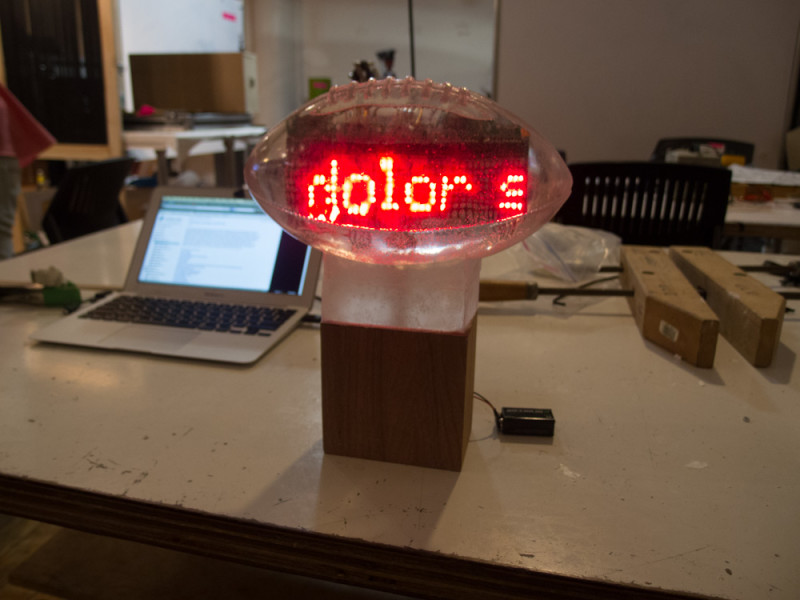
One thing professional moldmakers do that I didn’t is use vacuum and/or pressure chambers to eliminate bubbles from the final product. This was simply because I don’t have access to any, and the materials I used are generally fine without them. There are a bunch of bubbles, especially on the underside of the trophy, but nothing that stops you from seeing the LEDs clearly.
The surface of the resin had a few other imperfections: the silkscreened label from the original football was still visible and any bubbles that were on the surface had a barely visible white ring around them. To remove these, I sanded the resin starting with 220 grit sandpaper and gradually working my way up to 2000 grit, then finishing with Novus plastic polish. There was a little tradeoff involved: I was unable to polish the resin back to how clear it was originally, however the imperfections are gone. Again, with the proper tools (mainly a buffing wheel), I should be able to get the trophy to be clearer than it was when I demolded it.
And to finish, our reliable mahogany base received two coats of polyurethane varnish. Voilà! Read on to part 2.
