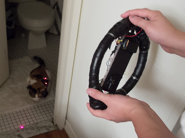
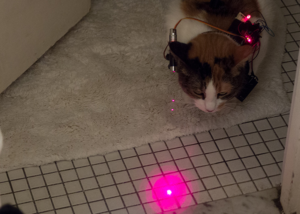
My final project for Phys Comp is Cat Car, a “Feline Fitness Frenzy!” It was intended as a cat exercise toy, however ultimately the cats I tested it on didn’t really care much for it. But that’s not the point! I learned quite a bit about accelerometers, gyroscopes and XBees along the way, which I’ll share here. Cat Car lets humans “drive” their cats by turning a laser pointer from side-to-side. The laser pointer is attached to a harness worn by the cat and its angle is determined by a steering wheel. The cat, wanting to follow the laser, will go where it is. We hope.
Before I get in to it, I want to mention that the safety and wellbeing of the cats involved was my top priority in testing this project. None of the cats were visibly discomforted by the harness, nor did they try to take it off or show any other sign that they were not having a good time. All three cats enjoyed the toy for a few minutes and then became bored, at which point I promptly took the harness off. Okay – on with it!
The Steering Wheel

The Steering Wheel is comprised of three main components: an Arduino, an MPU6050 gyroscope/accelerometer (an intertial measurement unit, or IMU) and an XBee Series 2 for wireless communication. I ran into a few problems with the IMU, mostly due to me trying to overcomplicate things. The goal of it is to get the left/right tilt of the steering wheel and map it to the servo, which seemed simple but proved challenging. In the end, my understanding of how everything works is probably mired with remnants of my overcomplication – but that’s how I learn!
Going back to the Arduino.cc page on the MPU6050 now, knowing what I know, everything makes sense and I’m curious why I didn’t just stick with it. But for whatever reason, I ventured out into the internet and came up with this post from Fabio Varesano which gave me access to the quaternion values that the IMU calculates based on the raw gyro/accelerometer values, instead of a higher-level abstraction that might be easier to work with. I hesitate to get into quaternions, Euler angles, gimbal lock and the like here because I’m totally unqualified to discuss it. Ultimately, I was able to understand enough of it to know it was way more than what I needed.
Ideally I would have measured the Z axis rotation of the IMU. Neither the Euler values nor the raw gyro and accelerometer values were exactly what I needed. They were subject to “false changes” when, for example, I would turn my entire body around. Standing in one position and tilting the steering wheel left and right would work, but when I turned around, the IMU reacted the same way as if I had tilted it. I’m fairly positive that quaternions hold the key to my ideal solution, but getting in to them seemed like a great undertaking for someone of my “casual appreciation of mathematics.”
In the middle of that huge brain-mess of attempted understanding came a hilarious coincidence in which I ran into Noah Zerkin, whose code was the basis for Fabio’s (his name is even still up there in the comments!), at a bar here in New York. So a major shout out to Noah for helping me make sense of it all, and you know, the next time you’re having trouble with something, go out to a bar and you might just run into the one guy who knows that one little chip inside-out.
The “it’ll work” solution that I ultimately ended up with was to take the raw Z-axis gyro values, pass it through a running average, and include a reset button to accommodate for gyroscope drift. The end code for the steering wheel looks like this:
// Using the I2C device class (I2Cdev) by Jeff Rowberg
// https://github.com/jrowberg/i2cdevlib

#include "Wire.h"
#include "I2Cdev.h"
#include "MPU6050.h"

MPU6050 accelgyro;

const int movingAvgSize = 10;
int movingAvg[movingAvgSize];
int movingAvgCounter = 0;
int runningOffset = 0;

int readyTime = 8000;
boolean ready = false;

#define LED_PIN 13
#define RESET_PIN 8

void setup() {
    Wire.begin();
    Serial.begin(9600);

    initMovingAvg();
    accelgyro.initialize();

    pinMode(LED_PIN, OUTPUT);
    pinMode(RESET_PIN, INPUT);
}

void loop() {
    if(!ready) {
      checkForReady();
      digitalWrite(LED_PIN, LOW);
    } else {
      digitalWrite(LED_PIN, HIGH);

      if(digitalRead(RESET_PIN)) runningOffset = 0;

      int rz = accelgyro.getRotationZ();
      rz = round(rz/128);
      pushMovingAverage(rz);

      int ma = getMovingAverage();
      runningOffset += ma;
      runningOffset = constrain(runningOffset, -5000, 5000);

      byte servoVal = map(runningOffset, 5000, -5000, , 180);
      Serial.write(servoVal);
    }
    delay(10);
}

void pushMovingAverage(int val) {
  movingAvg[movingAvgCounter] = val;
  movingAvgCounter++;
  if(movingAvgCounter >= movingAvgSize) movingAvgCounter = 0;
}

int getMovingAverage() {
  int total = 0;

  for(int i=; i<movingAvgSize; i++) {
    total += movingAvg[i];
  }

  return round(total / movingAvgSize);
}

void initMovingAvg() {
  for(int i=; i<movingAvgSize; i++) {
    movingAvg[i] = 0;
  }
}

void checkForReady() {
  if(millis() > readyTime) {
    ready = true;
    digitalWrite(LED_PIN, HIGH);
  }
}
The Harness

The code for the harness was much simpler and I won’t explain it much. Basically it reads the serial value coming from the XBee and sends it out to the servo. It looks like this:
#include "Servo.h"

Servo servo;

void setup() {
  Serial.begin(9600);
  servo.attach(10);
  servo.write(90);
  pinMode(13, OUTPUT);
}

void loop() {
  if (Serial.available() > ) {
    byte incomingByte = Serial.read();
    servo.write(constrain(incomingByte, , 179));
    digitalWrite(13, LOW);
  } else {
    digitalWrite(13, HIGH);
  }

  delay(10);
}
The XBees
The last thing to mention are the XBees. They ended up being fairly straightforward – I initially used this walkthrough, which was good for introducing the concepts of multiple firmwares to build on AT communication, which we had covered in class. The XBee on the steering wheel is set as the coordinator and the one on the harness is set as the end device. The value that gets sent over is the servo’s angle, an integer from 0 to 179.
The Whole Shebang!
I tested the system on three cats and got three different reactions. One cat was indifferent and two were kind of into it. I think maybe with more training time I might be able to lead the cat in long, serpentine paths, but as we all know, cats are going to do whatever they want to do and they all ended up being bored after a few minutes. You can see this in the video up top. Next steps for the project might include a more powerful laser and the subsequent assembly of a cyborg-cat army.
Update: The project got picked up on Engadget – check it out here! You can see my setup at the show and hear me talk about it for a bit.